QR code decoding
Invented in 1994 by Japanese company Denso-wave (major funding Denso corp., minor funding Toyota). Quickly entered standardization process, becoming ISO/IEC international standard in 2000. Current version is QR Code Model 2005.
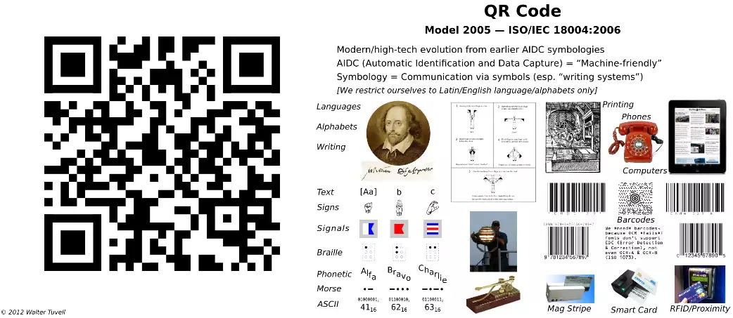
Royalty-free usage, worldwide. For commercial use, hardware scanners available in several technologies; no more expensive than other barcode scanners. For casual use, software generators and readers are cheaply/freely available; apps for PCs and cell phones (working with images or cameras), and even web resources.
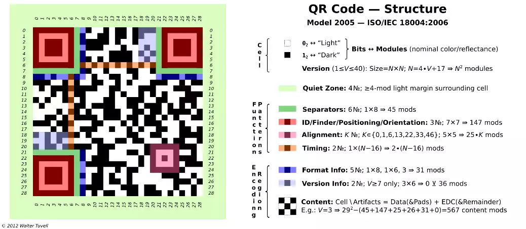
"Light"/"dark" are understood relative to per-symbol global threshold (reflectance midway between minimum and maximum for the symbol). Polarity can be reversed (02⟷"dark", 12⟷"light")- if decoder cannot locate finder patterns, try reversing polarity can be valid). Other variations may also be supported, depending on the reader/decoder (e.g. physical/3D markings, such as dice-like dot/peen dimples). Easiy depicted in ASCII, too (using *, ⊔). Corner features (quiet zone, finder patterns, separators) enable identification, location, rotational orientation, reflectance polarity. Timing patterns (alternating reflectance) support symbol density, version/size to be determined, and provide positions for determining row/col coordinates (rectangular, not just square).
Alignment patterns, located symmetrically about diagonal, support symbol distortions to be detected/corrected. № 0 (V=1); 1 (2≤V≤6); 6 (7≤V≤13); 13 (14≤V≤20); 22 (21≤V≤27); 33 (28≤V≤34); 46 (35≤V≤40).
Version info: 7≤V≤40 only (not present in our smaple); 2 copies, each 18 bits (6 data, 12 EDC); encodes value V ; specia-snake/zigzag layout; unmasked. Version info EDC uses binary Golary 18,6 ECC (≤3-bit correction). The F2[x] polynomial of degree ≤ 6 whose coefficients are bits 17-12 (which encode V), multipled by X18-6=X12, is divided by designated generator polynomial X12+X11+X10+X9X+8X+5X+2+1, and the remainder polynomial's coefficients are taken as bits 11-0. See ISO/IEC spec, §D.2, for error detection/correction procedure.
Damage to fixed patterns (deviation from ideal appearance of corner features, timing patterns, alignment patterns) can be evaluated, for quality control purposes (see ISO/IEC 15415 Print Quality specification).
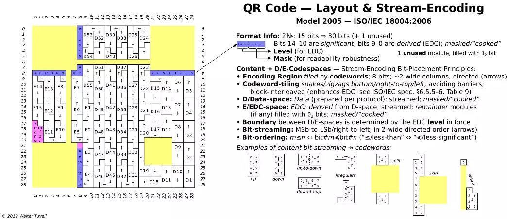
The unused module is marked dark (and not masked). "Snake" refers to byte-level layout; "zigzag" refers to bit-level layout. Layout/boundaries of D/E codewords is not to be confused with layout/boundaries of encoded charset SDD entities (see below). Format info EDC uses BCH (Bose-Chaudhuri-Hocquenghem) 15,5 ECC (≤3 bit correction). The F2[X] polynomial of degree ≤ 5 whose coefficients are bits 14-10 (level, mask), multiplied by X15-5=X10, is divided by designated generator polyno mial X10+X8+X5+X4+X2+X+1, and the remainder polynomial's coefficients are taken as bits 9-0. See ISO/IEC spec, §C.2, for error detection/correction procedure. Upon decoding, if format info doesn't validate, try mirror-reversal of symbol (= transpose about diagonal, exchanging rows and columns - which reverses the format into bits provided the value of bit 7 is 12, but forces bit 7 to be regarded as an error if bit 7 is 02). Both mirror images cannot be valid, to within 2 errors, due to design of format info pattern (by inspection of ISO/IEC spec Table C.1, no reversal of a valid format info string is also a valid string, to within 2 errors).
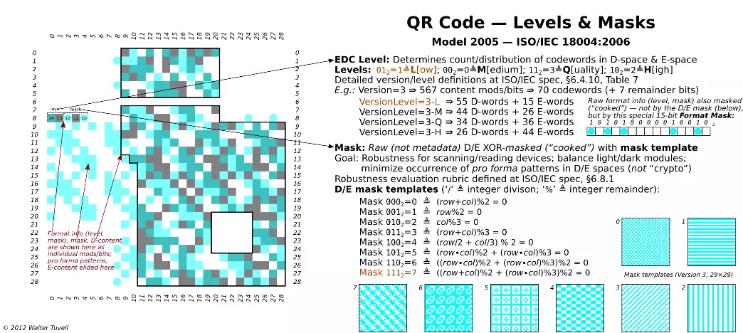
The special mask 101,0100,0001,00102 ensures that masked/cooked format info is never all-0's. D-space EDC uses RS (Reed-Solomon) c, k, r (for various values of c, k, r; see ISO/IEC spec, Table 9) ECC, over F256=GF(28). The irreducible primitive polynomial defining F256 itself is taken to be X8+X4+X3+X2+1. 36 different generating polynomials are used (ISO/IEC spec, Table A.1). Error-correction percentages in ~ 7 ½% increments: approx. 7½/15/22½/30. See ISO/IEC spec, §6.5.2 and Annexes A-B for error-code generation and error detection/correction procedure.
F256-based scheme requires blocking: D-space must be initially partioned into a number of blocks, of specified sizes (definied in ISO/IEC spec, Table 9); then each D-block is mapped to a corresponding E-block via ECC generation. Eddect of blocking on placement of codewords is specified by ISO/IEC spec, §6.6 and Figure 15 (e.g., shortest block(s), if any, are placed first).
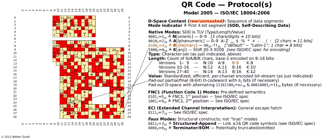
The concatenated padding ec16||1116||ec16||... contains runs of 1/2/3/4/5
single binary digits (02, 12).
FNC1 support compatibility with external industrial barcode standards, esp. Code 128 ("position 1" = GS1 General Specification;
"position 2" = AIM Inc.).
ECI (defined by AIM Inc., Association for Automatic Identification and Mobility) supports consistent technique for associating semantics
to data. By "default" (i.e., if no explicit ECI directive is present, and native type B[yte|inary] is in effect), the content is to
be interpreted as ISO/IEC 8859-1 ("Latin-1"). If ECI mode indicator (4 bits, 01112=716) is present, it is followed by 8/16/24-bit
ECI Designator (defined by AIM), followed by data (in TLV format). It functions as a general "escape hatch" (e.g., it can indicate compression
or encryption).
Structured-Append SDD: All symbols in the chain begin with structured-append header:
- 00112=316 (4 bits)
- 4-bit binary-encoded value (0-15) of "this" link in chain
- 4-bit binary-encoded value (0-15) of length of chain
- 8 bits of parity/checksum data, XOR of all bytes of raw input data for the chain (this associates all links as being in common chain)
Upon decoding, our sample QR code symbol yields the following content:
Mr. Watson, come here - I want to see you.
Source: Wikipedia.com
More information

 Sign in