QR code structure
This guide helps you understand the structure of the qr code. It explains the shape, the parts and the layout of a common QR code. After reading this article you will understand what are all the lines, bits and modules in a QR code.


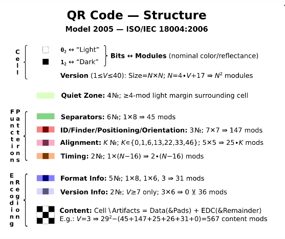
"Light"/"dark" are understood relative to per-symbol global threshold (reflectance midway between minimum and maximum for the symbol). Polarity can be reversed (02⟷"dark", 12⟷"light") - if decoder cannot locate finder patterns, try reversing polarity (only one polarity can be valid). Other variations may also be supported, depending on the reader/decoder (e.g., physical/3D markings, such as dice-like dot/peen dimples). Easily depicted in ASCII, too (using *, ⊔).
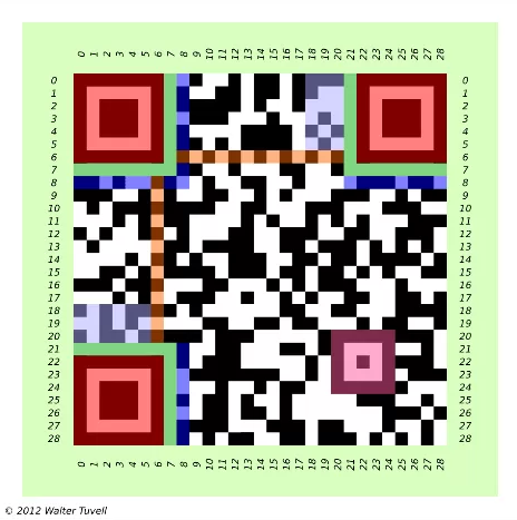
Corner features (quiet zone, finder patterns, separators) enable identification, location, rotational orientation, reflectance polarity.
Timing patterns (alternating reflectance) supports symbol density, version/size to be determined, and provide positions for determining row/col coordinates (rectangular, not just square).
Alignment patterns, located symmetrically about diagonal, supports symbol distortions to be detected/corrected. №: 0(V=1); 1 (2≤V≤6); 6 (7≤V≤13); 13 (14≤V≤20); 22 (21≤V≤34); 46 (35≤V≤40).
Version info: 7≤V≤40 only (not present in our sample); 2 copies, each 18 bits (6 data, 12 EDC); encodes value V ; special-snake/zigzag layout; unmasked.
Version info EDC uses binary Golay 18,6 ECC (≤3-bit correction). The F2 [X] polynomial of degree ≤ 6 whose coefficients are bits 17-12 (which encode V), multiplied by X18-6=X12, is divided by designated generator polynomial X12+X11+X10+X9+X8+X5+X2+1, and the remainder polynomial's coefficients are taken as bits 11-0. See ISO/IEC spec, §D.2, for error detection/correction procedure.
Damage to fixed patterns (deviation from ideal appearance of corner features, timing patterns, alignment patterns) can be evaluated, for quality control purposes (see ISO/IEC 15415 Print Quality specification).
A QR code is made up from an array of black and white squares. There are 3 special squares that are larger than the rest. These are used for the image sensor to position itself. These large squares on three of the corners help the scanner app to figure out the orientation of the code and the possible distortion that comes from the fact that the scanner is held at angle.
The smaller black ans white blocks (the smaller cells) contain version and format information as well as the data itself. Some of the squares contain information used for error correction. This information is often referred to as redundancy.
More information

 Sign in